Saltar al contenido principal
LibreTexts Español

4.7: Consideraciones multimodales para guías de ondas coplanares

  • Page ID
    82058
  • \( \newcommand{\vecs}[1]{\overset { \scriptstyle \rightharpoonup} {\mathbf{#1}} } \)

    \( \newcommand{\vecd}[1]{\overset{-\!-\!\rightharpoonup}{\vphantom{a}\smash {#1}}} \)

    \( \newcommand{\id}{\mathrm{id}}\) \( \newcommand{\Span}{\mathrm{span}}\)

    ( \newcommand{\kernel}{\mathrm{null}\,}\) \( \newcommand{\range}{\mathrm{range}\,}\)

    \( \newcommand{\RealPart}{\mathrm{Re}}\) \( \newcommand{\ImaginaryPart}{\mathrm{Im}}\)

    \( \newcommand{\Argument}{\mathrm{Arg}}\) \( \newcommand{\norm}[1]{\| #1 \|}\)

    \( \newcommand{\inner}[2]{\langle #1, #2 \rangle}\)

    \( \newcommand{\Span}{\mathrm{span}}\)

    \( \newcommand{\id}{\mathrm{id}}\)

    \( \newcommand{\Span}{\mathrm{span}}\)

    \( \newcommand{\kernel}{\mathrm{null}\,}\)

    \( \newcommand{\range}{\mathrm{range}\,}\)

    \( \newcommand{\RealPart}{\mathrm{Re}}\)

    \( \newcommand{\ImaginaryPart}{\mathrm{Im}}\)

    \( \newcommand{\Argument}{\mathrm{Arg}}\)

    \( \newcommand{\norm}[1]{\| #1 \|}\)

    \( \newcommand{\inner}[2]{\langle #1, #2 \rangle}\)

    \( \newcommand{\Span}{\mathrm{span}}\) \( \newcommand{\AA}{\unicode[.8,0]{x212B}}\)

    \( \newcommand{\vectorA}[1]{\vec{#1}}      % arrow\)

    \( \newcommand{\vectorAt}[1]{\vec{\text{#1}}}      % arrow\)

    \( \newcommand{\vectorB}[1]{\overset { \scriptstyle \rightharpoonup} {\mathbf{#1}} } \)

    \( \newcommand{\vectorC}[1]{\textbf{#1}} \)

    \( \newcommand{\vectorD}[1]{\overrightarrow{#1}} \)

    \( \newcommand{\vectorDt}[1]{\overrightarrow{\text{#1}}} \)

    \( \newcommand{\vectE}[1]{\overset{-\!-\!\rightharpoonup}{\vphantom{a}\smash{\mathbf {#1}}}} \)

    \( \newcommand{\vecs}[1]{\overset { \scriptstyle \rightharpoonup} {\mathbf{#1}} } \)

    \( \newcommand{\vecd}[1]{\overset{-\!-\!\rightharpoonup}{\vphantom{a}\smash {#1}}} \)

    \(\newcommand{\avec}{\mathbf a}\) \(\newcommand{\bvec}{\mathbf b}\) \(\newcommand{\cvec}{\mathbf c}\) \(\newcommand{\dvec}{\mathbf d}\) \(\newcommand{\dtil}{\widetilde{\mathbf d}}\) \(\newcommand{\evec}{\mathbf e}\) \(\newcommand{\fvec}{\mathbf f}\) \(\newcommand{\nvec}{\mathbf n}\) \(\newcommand{\pvec}{\mathbf p}\) \(\newcommand{\qvec}{\mathbf q}\) \(\newcommand{\svec}{\mathbf s}\) \(\newcommand{\tvec}{\mathbf t}\) \(\newcommand{\uvec}{\mathbf u}\) \(\newcommand{\vvec}{\mathbf v}\) \(\newcommand{\wvec}{\mathbf w}\) \(\newcommand{\xvec}{\mathbf x}\) \(\newcommand{\yvec}{\mathbf y}\) \(\newcommand{\zvec}{\mathbf z}\) \(\newcommand{\rvec}{\mathbf r}\) \(\newcommand{\mvec}{\mathbf m}\) \(\newcommand{\zerovec}{\mathbf 0}\) \(\newcommand{\onevec}{\mathbf 1}\) \(\newcommand{\real}{\mathbb R}\) \(\newcommand{\twovec}[2]{\left[\begin{array}{r}#1 \\ #2 \end{array}\right]}\) \(\newcommand{\ctwovec}[2]{\left[\begin{array}{c}#1 \\ #2 \end{array}\right]}\) \(\newcommand{\threevec}[3]{\left[\begin{array}{r}#1 \\ #2 \\ #3 \end{array}\right]}\) \(\newcommand{\cthreevec}[3]{\left[\begin{array}{c}#1 \\ #2 \\ #3 \end{array}\right]}\) \(\newcommand{\fourvec}[4]{\left[\begin{array}{r}#1 \\ #2 \\ #3 \\ #4 \end{array}\right]}\) \(\newcommand{\cfourvec}[4]{\left[\begin{array}{c}#1 \\ #2 \\ #3 \\ #4 \end{array}\right]}\) \(\newcommand{\fivevec}[5]{\left[\begin{array}{r}#1 \\ #2 \\ #3 \\ #4 \\ #5 \\ \end{array}\right]}\) \(\newcommand{\cfivevec}[5]{\left[\begin{array}{c}#1 \\ #2 \\ #3 \\ #4 \\ #5 \\ \end{array}\right]}\) \(\newcommand{\mattwo}[4]{\left[\begin{array}{rr}#1 \amp #2 \\ #3 \amp #4 \\ \end{array}\right]}\) \(\newcommand{\laspan}[1]{\text{Span}\{#1\}}\) \(\newcommand{\bcal}{\cal B}\) \(\newcommand{\ccal}{\cal C}\) \(\newcommand{\scal}{\cal S}\) \(\newcommand{\wcal}{\cal W}\) \(\newcommand{\ecal}{\cal E}\) \(\newcommand{\coords}[2]{\left\{#1\right\}_{#2}}\) \(\newcommand{\gray}[1]{\color{gray}{#1}}\) \(\newcommand{\lgray}[1]{\color{lightgray}{#1}}\) \(\newcommand{\rank}{\operatorname{rank}}\) \(\newcommand{\row}{\text{Row}}\) \(\newcommand{\col}{\text{Col}}\) \(\renewcommand{\row}{\text{Row}}\) \(\newcommand{\nul}{\text{Nul}}\) \(\newcommand{\var}{\text{Var}}\) \(\newcommand{\corr}{\text{corr}}\) \(\newcommand{\len}[1]{\left|#1\right|}\) \(\newcommand{\bbar}{\overline{\bvec}}\) \(\newcommand{\bhat}{\widehat{\bvec}}\) \(\newcommand{\bperp}{\bvec^\perp}\) \(\newcommand{\xhat}{\widehat{\xvec}}\) \(\newcommand{\vhat}{\widehat{\vvec}}\) \(\newcommand{\uhat}{\widehat{\uvec}}\) \(\newcommand{\what}{\widehat{\wvec}}\) \(\newcommand{\Sighat}{\widehat{\Sigma}}\) \(\newcommand{\lt}{<}\) \(\newcommand{\gt}{>}\) \(\newcommand{\amp}{&}\) \(\definecolor{fillinmathshade}{gray}{0.9}\)

    La orientación del campo en CPW se ve poco afectada cuando la frecuencia aumenta y como tal la permitividad efectiva de CPW tiene poca dependencia de frecuencia. (Esto está en marcado contraste con la microtira.) Por lo tanto, la dispersión dieléctrica de CPW es mínima y esta es una de las principales ventajas de usar CPW sobre microbanda. CPW tiene la resistencia de línea dependiente de la frecuencia

    \[\label{eq:1}R(f)=\left\{\begin{array}{ll}{R(0)}&{f\text{ such that }t\leq 3\delta_{s}}\\{R(0)+R_{\text{skin}}(f)}&{f\text{ such that }t>3\delta_{s}}\end{array}\right. \]

    donde\(R(0) (= R_{\text{strip}}(0) + R_{\text{ground}}(0))\) está la resistencia de la línea a bajas frecuencias. \(R(f)\)describe la resistencia de la línea dependiente de la frecuencia, que se debe tanto al efecto de la piel como al agrupamiento actual. Aproximadamente,

    \[\label{eq:2}R_{\text{skin}}(f)=R(0)k\sqrt{f} \]

    donde\(k\) es una constante. Al igual que con microstrip, se recomiendan simulaciones EM para determinar la pérdida de línea. Esto es necesario en cualquier caso para determinar la atenuación debida a la radiación, la cual puede ser ignorada a bajas frecuencias de microondas.

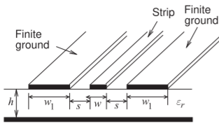
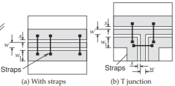
    La discusión del multimodo sobre CPW considerará la estructura de CPW de tierra finita (FGCPW) mostrada en la Figura\(\PageIndex{1}\). La mayoría de las consideraciones relacionadas con el multimodo en microcinta se aplican a FGCPW. Sin embargo, con CPW los campos penetran en el sustrato una distancia menor y por lo tanto es menos probable que el modo sustrato o el modo microbanda se exciten. Para evitar el modo de microcinta, el FGCPW debe estar a una distancia suficiente del plano de tierra inferior. Generalmente es suficiente una altura del sustrato tres o más veces tanto el espacio como el ancho de la tira. Un modo que puede existir en FGCPW que no tiene un equivalente con microcinta ocurre cuando las tiras de tierra a ambos lados de la tira central adquieren diferentes voltajes. El correcto funcionamiento de FGCPW requiere que estos estén al mismo potencial. La solución es conectar las dos tiras laterales entre sí usando correas de conexión a tierra como se muestra en la Figura\(\PageIndex{2}\) (a). Las correas se realizan usando cables de unión si FGCPW se usa en una placa de circuito, o usando puentes aéreos si la línea está en un circuito integrado monolítico. Colocar las tiras a distancias de aproximadamente un cuarto de longitud de onda es apropiado, aunque esto se puede relajar si la línea
    clipboard_ebf46f15b18ecc788cbf1a84fc660cd9d.png

    Figura\(\PageIndex{1}\): Línea de transmisión CPW de tierra finita.
    clipboard_e254f425c8ff5fce9e587a508a579ff91.png

    Figura\(\PageIndex{2}\): Estructuras CPW con bandas de tierra para suprimir el modo de placa paralela.
    clipboard_e727a476b046a5a5809551319adce0fa4.png

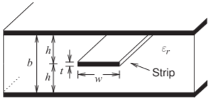
    Figura\(\PageIndex{3}\): Línea de transmisión Stripline.

    está bastante libre de discontinuidades. Las correas deben colocarse al azar para evitar cualquier efecto filtrante que pudiera resultar de colocar las correas a intervalos regulares. Las correas también deben usarse siempre que haya una discontinuidad (ver, por ejemplo, la unión en la Figura\(\PageIndex{2}\) (b)).


    This page titled 4.7: Consideraciones multimodales para guías de ondas coplanares is shared under a not declared license and was authored, remixed, and/or curated by Michael Steer.