Saltar al contenido principal
LibreTexts Español

9.3.4: Estudio de la figura interferencial

  • Page ID
    51184
  • \( \newcommand{\vecs}[1]{\overset { \scriptstyle \rightharpoonup} {\mathbf{#1}} } \)

    \( \newcommand{\vecd}[1]{\overset{-\!-\!\rightharpoonup}{\vphantom{a}\smash {#1}}} \)

    \( \newcommand{\id}{\mathrm{id}}\) \( \newcommand{\Span}{\mathrm{span}}\)

    ( \newcommand{\kernel}{\mathrm{null}\,}\) \( \newcommand{\range}{\mathrm{range}\,}\)

    \( \newcommand{\RealPart}{\mathrm{Re}}\) \( \newcommand{\ImaginaryPart}{\mathrm{Im}}\)

    \( \newcommand{\Argument}{\mathrm{Arg}}\) \( \newcommand{\norm}[1]{\| #1 \|}\)

    \( \newcommand{\inner}[2]{\langle #1, #2 \rangle}\)

    \( \newcommand{\Span}{\mathrm{span}}\)

    \( \newcommand{\id}{\mathrm{id}}\)

    \( \newcommand{\Span}{\mathrm{span}}\)

    \( \newcommand{\kernel}{\mathrm{null}\,}\)

    \( \newcommand{\range}{\mathrm{range}\,}\)

    \( \newcommand{\RealPart}{\mathrm{Re}}\)

    \( \newcommand{\ImaginaryPart}{\mathrm{Im}}\)

    \( \newcommand{\Argument}{\mathrm{Arg}}\)

    \( \newcommand{\norm}[1]{\| #1 \|}\)

    \( \newcommand{\inner}[2]{\langle #1, #2 \rangle}\)

    \( \newcommand{\Span}{\mathrm{span}}\) \( \newcommand{\AA}{\unicode[.8,0]{x212B}}\)

    \( \newcommand{\vectorA}[1]{\vec{#1}}      % arrow\)

    \( \newcommand{\vectorAt}[1]{\vec{\text{#1}}}      % arrow\)

    \( \newcommand{\vectorB}[1]{\overset { \scriptstyle \rightharpoonup} {\mathbf{#1}} } \)

    \( \newcommand{\vectorC}[1]{\textbf{#1}} \)

    \( \newcommand{\vectorD}[1]{\overrightarrow{#1}} \)

    \( \newcommand{\vectorDt}[1]{\overrightarrow{\text{#1}}} \)

    \( \newcommand{\vectE}[1]{\overset{-\!-\!\rightharpoonup}{\vphantom{a}\smash{\mathbf {#1}}}} \)

    \( \newcommand{\vecs}[1]{\overset { \scriptstyle \rightharpoonup} {\mathbf{#1}} } \)

    \( \newcommand{\vecd}[1]{\overset{-\!-\!\rightharpoonup}{\vphantom{a}\smash {#1}}} \)

    \(\newcommand{\avec}{\mathbf a}\) \(\newcommand{\bvec}{\mathbf b}\) \(\newcommand{\cvec}{\mathbf c}\) \(\newcommand{\dvec}{\mathbf d}\) \(\newcommand{\dtil}{\widetilde{\mathbf d}}\) \(\newcommand{\evec}{\mathbf e}\) \(\newcommand{\fvec}{\mathbf f}\) \(\newcommand{\nvec}{\mathbf n}\) \(\newcommand{\pvec}{\mathbf p}\) \(\newcommand{\qvec}{\mathbf q}\) \(\newcommand{\svec}{\mathbf s}\) \(\newcommand{\tvec}{\mathbf t}\) \(\newcommand{\uvec}{\mathbf u}\) \(\newcommand{\vvec}{\mathbf v}\) \(\newcommand{\wvec}{\mathbf w}\) \(\newcommand{\xvec}{\mathbf x}\) \(\newcommand{\yvec}{\mathbf y}\) \(\newcommand{\zvec}{\mathbf z}\) \(\newcommand{\rvec}{\mathbf r}\) \(\newcommand{\mvec}{\mathbf m}\) \(\newcommand{\zerovec}{\mathbf 0}\) \(\newcommand{\onevec}{\mathbf 1}\) \(\newcommand{\real}{\mathbb R}\) \(\newcommand{\twovec}[2]{\left[\begin{array}{r}#1 \\ #2 \end{array}\right]}\) \(\newcommand{\ctwovec}[2]{\left[\begin{array}{c}#1 \\ #2 \end{array}\right]}\) \(\newcommand{\threevec}[3]{\left[\begin{array}{r}#1 \\ #2 \\ #3 \end{array}\right]}\) \(\newcommand{\cthreevec}[3]{\left[\begin{array}{c}#1 \\ #2 \\ #3 \end{array}\right]}\) \(\newcommand{\fourvec}[4]{\left[\begin{array}{r}#1 \\ #2 \\ #3 \\ #4 \end{array}\right]}\) \(\newcommand{\cfourvec}[4]{\left[\begin{array}{c}#1 \\ #2 \\ #3 \\ #4 \end{array}\right]}\) \(\newcommand{\fivevec}[5]{\left[\begin{array}{r}#1 \\ #2 \\ #3 \\ #4 \\ #5 \\ \end{array}\right]}\) \(\newcommand{\cfivevec}[5]{\left[\begin{array}{c}#1 \\ #2 \\ #3 \\ #4 \\ #5 \\ \end{array}\right]}\) \(\newcommand{\mattwo}[4]{\left[\begin{array}{rr}#1 \amp #2 \\ #3 \amp #4 \\ \end{array}\right]}\) \(\newcommand{\laspan}[1]{\text{Span}\{#1\}}\) \(\newcommand{\bcal}{\cal B}\) \(\newcommand{\ccal}{\cal C}\) \(\newcommand{\scal}{\cal S}\) \(\newcommand{\wcal}{\cal W}\) \(\newcommand{\ecal}{\cal E}\) \(\newcommand{\coords}[2]{\left\{#1\right\}_{#2}}\) \(\newcommand{\gray}[1]{\color{gray}{#1}}\) \(\newcommand{\lgray}[1]{\color{lightgray}{#1}}\) \(\newcommand{\rank}{\operatorname{rank}}\) \(\newcommand{\row}{\text{Row}}\) \(\newcommand{\col}{\text{Col}}\) \(\renewcommand{\row}{\text{Row}}\) \(\newcommand{\nul}{\text{Nul}}\) \(\newcommand{\var}{\text{Var}}\) \(\newcommand{\corr}{\text{corr}}\) \(\newcommand{\len}[1]{\left|#1\right|}\) \(\newcommand{\bbar}{\overline{\bvec}}\) \(\newcommand{\bhat}{\widehat{\bvec}}\) \(\newcommand{\bperp}{\bvec^\perp}\) \(\newcommand{\xhat}{\widehat{\xvec}}\) \(\newcommand{\vhat}{\widehat{\vvec}}\) \(\newcommand{\uhat}{\widehat{\uvec}}\) \(\newcommand{\what}{\widehat{\wvec}}\) \(\newcommand{\Sighat}{\widehat{\Sigma}}\) \(\newcommand{\lt}{<}\) \(\newcommand{\gt}{>}\) \(\newcommand{\amp}{&}\) \(\definecolor{fillinmathshade}{gray}{0.9}\)

    La diferencia de fases \(k\left(r_{2}-r_{1}\right)\) es, esencialmente, una diferencia de camino óptico:

    \[
    \frac{2 \pi}{\lambda} n\left(r_{2}-r_{1}\right)=\frac{2 \pi}{\lambda}\left(\mathcal{L}\left(O \rightarrow o_{2} \rightarrow P\right)-\mathcal{L}\left(O \rightarrow o_{1} \rightarrow P\right)\right) \notag
    \]

    donde \(\mathcal{L}\) es el funcional camino óptico. La diferencia de fases se puede escribir en función del tiempo que tarda en llegar a la pantalla lo que ha sido emitido simultáneamente. En efecto, utilizando el hecho de que \(v_{f}=\frac{c}{n}\)

    \[
    k\left(r_{2}-r_{1}\right)=\frac{\omega}{c} n\left(r_{2}-r_{1}\right)=\omega\left(\tau_{2}-\tau_{1}\right) \notag
    \]

    Para estudiar el aspecto de la figura interferencial es conveniente hacer dos hipótesis y dos aproximaciones:

    1. (hipótesis) Las aberturas tienen que estar próximas entre sí, y el punto \(P\) debe estar pŕoximo al eje óptico si queremos que el retardo entre las dos ondas no sea tan grande que se destruya la interferencia. Estas hipótesis se traducen en

    \[
    \begin{aligned}
    d & \ll D \\
    x, y & \ll D
    \end{aligned}
    \]

    2. (aproximaciones) Recordemos que \(r_{1}, r_{2}\) aparece en dos sitios con un papel muy diferente: en las intensidades \(I_{1}, I_{2}\) la dependencia es muy suave, mientras que en la fase la dependencia es acusada, por ser \(k\) muy grande para la luz visible.

    a) Tomaremos como aproximación para fuera de la función trigonométrica

    \[
    r_{1} \simeq r_{2} \simeq D \notag
    \]

    lo que implica que \(I_{1} \simeq I_{2} \simeq I_{0}\).

    b) Usaremos un orden de aproximación mayor para el argumento del coseno

    \[
    \begin{aligned}
    r_{1} &=D \sqrt{1+\frac{y^{2}+\left(x-\frac{d}{2}\right)^{2}}{D^{2}}} \\
    & \simeq D+\frac{y^{2}+x^{2}+\frac{d^{2}}{4}-x d}{2 D}
    \end{aligned}
    \]

    análogamente para

    \[
    r_{2} \simeq D+\frac{y^{2}+x^{2}+\frac{d^{2}}{4}+x d}{2 D} \notag
    \]

    con lo que

    \[
    r_{2}-r_{1}=\frac{x d}{D} \notag
    \]

    Si el interferómetro se encuentra en el vacío \(n=1\) y finalmente la expresión para la interferencia resulta

    \[
    I=2 I_{0}\left(1+\cos \left(\frac{2 \pi}{\lambda} \frac{x d}{D}\right)\right) \notag
    \]

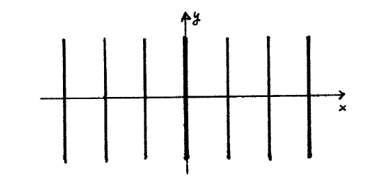
    para caracterizar la figura es interesante localizar los máximos y mínimos de intensidad.
    clipboard_e665fd3a7bbe1c75556e774a8da29afa4.png
    Figura \(\PageIndex{1}\): En la zona central de la pantalla de observación los máximos son líneas verticales paralelas con separación de \(\frac{\lambda D}{d}\).
    clipboard_eeb0b3c5f55585cf600f5c589ac4329d2.png
    Figura \(\PageIndex{2}\): Las rectas devienen hipérbolas si consideramos una zona mayor de la pantalla de observación.
    • Máximos:

    \[
    \frac{2 \pi}{\lambda} \frac{x d}{D}=2 \pi M \notag
    \]

    con \(M \in \mathcal{Z} .\) Al valor de \(M\) se le llama orden del máximo correspondiente. La coordenada del máximo de orden \(M\) es

    \[
    x_{M}=M \frac{\lambda D}{d} \notag
    \]

    y se cumple \(I_{\max }=4 I_{0}\). \notag

    • Mínimos:

    \[
    \frac{2 \pi}{\lambda} \frac{x d}{D}=(2 m+1) \pi \notag
    \]

    \(\operatorname{con} m \in \mathcal{Z}\) e \(I_{\min }=0\)

    Observaciones

    • Recordemos que esto sólo vale para \(d\) pequeñas y zonas próximas al eje \(z\) (véase la figura \(9.7\) ).
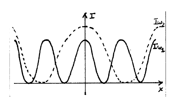
    • La posición de los máximos depende de la longitud de onda, por lo que sabiendo las dimensiones del dispositivo se pueden medir longitudes de onda de modo preciso. Recíprocamente, la interferencia puede servir para medir la separación entre dos fuentes puntuales si se conoce la longitud de onda con que emiten.
    clipboard_e616f6c19fcb97ede42061a0f078896a9.png
    Figura \(\PageIndex{3}\): Distribución de intensidad para luz monocromática de , \(I_{\omega_{1}}(x)\) e \(I_{\omega_{2}}(x)\), con \(I_{\omega_{1}}(x) \neq\) \(I_{\omega_{2}}(x)\).

    Visibilidad

    se define la visibilidad de una figura de interferencia como

    \[
    V=\frac{I_{\max }-I_{\min }}{I_{\max }+I_{\min }} \notag
    \]

    se calcula midiendo la intensidad en un máximo y en su mínimo adyacente.

    • \(V=1\) ocurre siempre que \(I_{1}=I_{2}\left(I_{\min }=0\right)\).
    • \(V=0\) corresponde a la mínima visibilidad, y ocurre cuando \(I_{\max }=I_{\min }\) (no hay interferencia).

    En el ejemplo que hemos tratado hemos obtenido \(V=1\) porque hemos utilizado dos ondas estrictamente armónicas. Vamos a ver que si consideramos ondas no monocromáticas la visibilidad desciende.


    9.3.4: Estudio de la figura interferencial is shared under a CC BY-SA 1.0 license and was authored, remixed, and/or curated by LibreTexts.