3.11: JFET
- Page ID
- 86340
\( \newcommand{\vecs}[1]{\overset { \scriptstyle \rightharpoonup} {\mathbf{#1}} } \)
\( \newcommand{\vecd}[1]{\overset{-\!-\!\rightharpoonup}{\vphantom{a}\smash {#1}}} \)
\( \newcommand{\dsum}{\displaystyle\sum\limits} \)
\( \newcommand{\dint}{\displaystyle\int\limits} \)
\( \newcommand{\dlim}{\displaystyle\lim\limits} \)
\( \newcommand{\id}{\mathrm{id}}\) \( \newcommand{\Span}{\mathrm{span}}\)
( \newcommand{\kernel}{\mathrm{null}\,}\) \( \newcommand{\range}{\mathrm{range}\,}\)
\( \newcommand{\RealPart}{\mathrm{Re}}\) \( \newcommand{\ImaginaryPart}{\mathrm{Im}}\)
\( \newcommand{\Argument}{\mathrm{Arg}}\) \( \newcommand{\norm}[1]{\| #1 \|}\)
\( \newcommand{\inner}[2]{\langle #1, #2 \rangle}\)
\( \newcommand{\Span}{\mathrm{span}}\)
\( \newcommand{\id}{\mathrm{id}}\)
\( \newcommand{\Span}{\mathrm{span}}\)
\( \newcommand{\kernel}{\mathrm{null}\,}\)
\( \newcommand{\range}{\mathrm{range}\,}\)
\( \newcommand{\RealPart}{\mathrm{Re}}\)
\( \newcommand{\ImaginaryPart}{\mathrm{Im}}\)
\( \newcommand{\Argument}{\mathrm{Arg}}\)
\( \newcommand{\norm}[1]{\| #1 \|}\)
\( \newcommand{\inner}[2]{\langle #1, #2 \rangle}\)
\( \newcommand{\Span}{\mathrm{span}}\) \( \newcommand{\AA}{\unicode[.8,0]{x212B}}\)
\( \newcommand{\vectorA}[1]{\vec{#1}} % arrow\)
\( \newcommand{\vectorAt}[1]{\vec{\text{#1}}} % arrow\)
\( \newcommand{\vectorB}[1]{\overset { \scriptstyle \rightharpoonup} {\mathbf{#1}} } \)
\( \newcommand{\vectorC}[1]{\textbf{#1}} \)
\( \newcommand{\vectorD}[1]{\overrightarrow{#1}} \)
\( \newcommand{\vectorDt}[1]{\overrightarrow{\text{#1}}} \)
\( \newcommand{\vectE}[1]{\overset{-\!-\!\rightharpoonup}{\vphantom{a}\smash{\mathbf {#1}}}} \)
\( \newcommand{\vecs}[1]{\overset { \scriptstyle \rightharpoonup} {\mathbf{#1}} } \)
\( \newcommand{\vecd}[1]{\overset{-\!-\!\rightharpoonup}{\vphantom{a}\smash {#1}}} \)
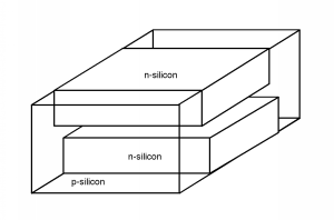
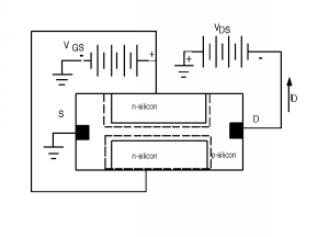
\(\newcommand{\avec}{\mathbf a}\) \(\newcommand{\bvec}{\mathbf b}\) \(\newcommand{\cvec}{\mathbf c}\) \(\newcommand{\dvec}{\mathbf d}\) \(\newcommand{\dtil}{\widetilde{\mathbf d}}\) \(\newcommand{\evec}{\mathbf e}\) \(\newcommand{\fvec}{\mathbf f}\) \(\newcommand{\nvec}{\mathbf n}\) \(\newcommand{\pvec}{\mathbf p}\) \(\newcommand{\qvec}{\mathbf q}\) \(\newcommand{\svec}{\mathbf s}\) \(\newcommand{\tvec}{\mathbf t}\) \(\newcommand{\uvec}{\mathbf u}\) \(\newcommand{\vvec}{\mathbf v}\) \(\newcommand{\wvec}{\mathbf w}\) \(\newcommand{\xvec}{\mathbf x}\) \(\newcommand{\yvec}{\mathbf y}\) \(\newcommand{\zvec}{\mathbf z}\) \(\newcommand{\rvec}{\mathbf r}\) \(\newcommand{\mvec}{\mathbf m}\) \(\newcommand{\zerovec}{\mathbf 0}\) \(\newcommand{\onevec}{\mathbf 1}\) \(\newcommand{\real}{\mathbb R}\) \(\newcommand{\twovec}[2]{\left[\begin{array}{r}#1 \\ #2 \end{array}\right]}\) \(\newcommand{\ctwovec}[2]{\left[\begin{array}{c}#1 \\ #2 \end{array}\right]}\) \(\newcommand{\threevec}[3]{\left[\begin{array}{r}#1 \\ #2 \\ #3 \end{array}\right]}\) \(\newcommand{\cthreevec}[3]{\left[\begin{array}{c}#1 \\ #2 \\ #3 \end{array}\right]}\) \(\newcommand{\fourvec}[4]{\left[\begin{array}{r}#1 \\ #2 \\ #3 \\ #4 \end{array}\right]}\) \(\newcommand{\cfourvec}[4]{\left[\begin{array}{c}#1 \\ #2 \\ #3 \\ #4 \end{array}\right]}\) \(\newcommand{\fivevec}[5]{\left[\begin{array}{r}#1 \\ #2 \\ #3 \\ #4 \\ #5 \\ \end{array}\right]}\) \(\newcommand{\cfivevec}[5]{\left[\begin{array}{c}#1 \\ #2 \\ #3 \\ #4 \\ #5 \\ \end{array}\right]}\) \(\newcommand{\mattwo}[4]{\left[\begin{array}{rr}#1 \amp #2 \\ #3 \amp #4 \\ \end{array}\right]}\) \(\newcommand{\laspan}[1]{\text{Span}\{#1\}}\) \(\newcommand{\bcal}{\cal B}\) \(\newcommand{\ccal}{\cal C}\) \(\newcommand{\scal}{\cal S}\) \(\newcommand{\wcal}{\cal W}\) \(\newcommand{\ecal}{\cal E}\) \(\newcommand{\coords}[2]{\left\{#1\right\}_{#2}}\) \(\newcommand{\gray}[1]{\color{gray}{#1}}\) \(\newcommand{\lgray}[1]{\color{lightgray}{#1}}\) \(\newcommand{\rank}{\operatorname{rank}}\) \(\newcommand{\row}{\text{Row}}\) \(\newcommand{\col}{\text{Col}}\) \(\renewcommand{\row}{\text{Row}}\) \(\newcommand{\nul}{\text{Nul}}\) \(\newcommand{\var}{\text{Var}}\) \(\newcommand{\corr}{\text{corr}}\) \(\newcommand{\len}[1]{\left|#1\right|}\) \(\newcommand{\bbar}{\overline{\bvec}}\) \(\newcommand{\bhat}{\widehat{\bvec}}\) \(\newcommand{\bperp}{\bvec^\perp}\) \(\newcommand{\xhat}{\widehat{\xvec}}\) \(\newcommand{\vhat}{\widehat{\vvec}}\) \(\newcommand{\uhat}{\widehat{\uvec}}\) \(\newcommand{\what}{\widehat{\wvec}}\) \(\newcommand{\Sighat}{\widehat{\Sigma}}\) \(\newcommand{\lt}{<}\) \(\newcommand{\gt}{>}\) \(\newcommand{\amp}{&}\) \(\definecolor{fillinmathshade}{gray}{0.9}\)Hay mucho más que podríamos hacer con los dispositivos de efecto de campo, pero probablemente sea el momento de pasar a nuevos temas. Para un punto final, sin embargo, podríamos mirar algo llamado el JFET, o transistor de efecto de campo de unión. La estructura JFET se parece a Figura\(\PageIndex{1}\). Consiste en una pieza de silicio tipo p, en la que se han difundido dos regiones tipo n. Sin embargo, en lugar de estar ambas en la misma superficie, como con un MOSFET, las dos regiones están opuestas entre sí a cada lado del cristal. En sección transversal, el JFET se parece a la Figura\(\PageIndex{2}\). También mostramos el sesgo aquí.


Las dos regiones n están conectadas entre sí y tienen polarización inversa con respecto al sustrato de tipo p. Una segunda batería,\(V_{\text{ds}}\), se utiliza para extraer corriente de la fuente mediante la aplicación de un voltaje negativo entre el drenaje y la fuente. Las uniones n-p polarizadas inversas crean una región de agotamiento que se extiende hacia el material tipo p a través del cual los orificios viajan a medida que van de la fuente al drenaje (¿un canal?). Al ajustar el valor de\(V_{\text{gs}}\), se puede hacer que la región de agotamiento sea más pequeña o más grande, aumentando o disminuyendo así la corriente de drenaje.
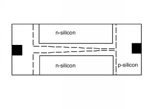
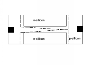
El estudiante observador también notará que la polaridad de la\(V_{\text{ds}}\) batería hace que haya más polarización inversa a través de las uniones p-n en el extremo de drenaje del canal que en el extremo fuente. Así, una representación más precisa del JFET sería lo que se muestra en la Figura\(\PageIndex{3}\). Cuando el voltaje de drenaje/fuente es lo suficientemente grande, las dos regiones de agotamiento se unirán entre sí y, al igual que con el MOSFET, el canal se pellizca, como se muestra en la Figura\(\PageIndex{4}\).


Por sorprendente que parezca, cuando trabajas las ecuaciones que describen cómo se extiende la región de agotamiento\(V_{\text{gs}}\) y cómo cambia el mecanismo de pinch-off\(I_{D}\), terminas con el comportamiento y ecuaciones, que son bastante similares a las de un MOSFET de modo de agotamiento.
El uso de JFET es un poco más engorroso que un MOSFET normal. Debe asegurarse de que la unión puerta-sustrato siempre permanezca polarizada inversa, y dado que el JFET solo puede ser un dispositivo de modo de agotamiento, debe tener un voltaje en la puerta si desea apagar el transistor. Sin embargo, el JFET sí tiene una ventaja sobre el MOSFET. Hace un tiempo calculamos el valor para\(C_{\text{ox}}\), la capacitancia de óxido, y encontramos que estaba en el orden de\(10^{-7} \ \frac{\mathrm{F}}{\mathrm{cm}^2}\). Una puerta MOSFET típica puede ser\(1 \ \mu \mathrm{m}\) larga por\(20 \ \mu \mathrm{m}\) amplia, por lo que tendría un área de puerta de\(20 \ \mu \mathrm{m}^{2}\) o\(2 \times 10^{-7} \ \mathrm{cm}^{2}\). Por lo tanto, la capacitancia total de la puerta es solo de aproximadamente\(10^{-14} \mathrm{~F}\).


