Saltar al contenido principal
LibreTexts Español

12.8: El catálisis

  • Page ID
    1900
  • \( \newcommand{\vecs}[1]{\overset { \scriptstyle \rightharpoonup} {\mathbf{#1}} } \)

    \( \newcommand{\vecd}[1]{\overset{-\!-\!\rightharpoonup}{\vphantom{a}\smash {#1}}} \)

    \( \newcommand{\id}{\mathrm{id}}\) \( \newcommand{\Span}{\mathrm{span}}\)

    ( \newcommand{\kernel}{\mathrm{null}\,}\) \( \newcommand{\range}{\mathrm{range}\,}\)

    \( \newcommand{\RealPart}{\mathrm{Re}}\) \( \newcommand{\ImaginaryPart}{\mathrm{Im}}\)

    \( \newcommand{\Argument}{\mathrm{Arg}}\) \( \newcommand{\norm}[1]{\| #1 \|}\)

    \( \newcommand{\inner}[2]{\langle #1, #2 \rangle}\)

    \( \newcommand{\Span}{\mathrm{span}}\)

    \( \newcommand{\id}{\mathrm{id}}\)

    \( \newcommand{\Span}{\mathrm{span}}\)

    \( \newcommand{\kernel}{\mathrm{null}\,}\)

    \( \newcommand{\range}{\mathrm{range}\,}\)

    \( \newcommand{\RealPart}{\mathrm{Re}}\)

    \( \newcommand{\ImaginaryPart}{\mathrm{Im}}\)

    \( \newcommand{\Argument}{\mathrm{Arg}}\)

    \( \newcommand{\norm}[1]{\| #1 \|}\)

    \( \newcommand{\inner}[2]{\langle #1, #2 \rangle}\)

    \( \newcommand{\Span}{\mathrm{span}}\) \( \newcommand{\AA}{\unicode[.8,0]{x212B}}\)

    \( \newcommand{\vectorA}[1]{\vec{#1}}      % arrow\)

    \( \newcommand{\vectorAt}[1]{\vec{\text{#1}}}      % arrow\)

    \( \newcommand{\vectorB}[1]{\overset { \scriptstyle \rightharpoonup} {\mathbf{#1}} } \)

    \( \newcommand{\vectorC}[1]{\textbf{#1}} \)

    \( \newcommand{\vectorD}[1]{\overrightarrow{#1}} \)

    \( \newcommand{\vectorDt}[1]{\overrightarrow{\text{#1}}} \)

    \( \newcommand{\vectE}[1]{\overset{-\!-\!\rightharpoonup}{\vphantom{a}\smash{\mathbf {#1}}}} \)

    \( \newcommand{\vecs}[1]{\overset { \scriptstyle \rightharpoonup} {\mathbf{#1}} } \)

    \( \newcommand{\vecd}[1]{\overset{-\!-\!\rightharpoonup}{\vphantom{a}\smash {#1}}} \)

    \(\newcommand{\avec}{\mathbf a}\) \(\newcommand{\bvec}{\mathbf b}\) \(\newcommand{\cvec}{\mathbf c}\) \(\newcommand{\dvec}{\mathbf d}\) \(\newcommand{\dtil}{\widetilde{\mathbf d}}\) \(\newcommand{\evec}{\mathbf e}\) \(\newcommand{\fvec}{\mathbf f}\) \(\newcommand{\nvec}{\mathbf n}\) \(\newcommand{\pvec}{\mathbf p}\) \(\newcommand{\qvec}{\mathbf q}\) \(\newcommand{\svec}{\mathbf s}\) \(\newcommand{\tvec}{\mathbf t}\) \(\newcommand{\uvec}{\mathbf u}\) \(\newcommand{\vvec}{\mathbf v}\) \(\newcommand{\wvec}{\mathbf w}\) \(\newcommand{\xvec}{\mathbf x}\) \(\newcommand{\yvec}{\mathbf y}\) \(\newcommand{\zvec}{\mathbf z}\) \(\newcommand{\rvec}{\mathbf r}\) \(\newcommand{\mvec}{\mathbf m}\) \(\newcommand{\zerovec}{\mathbf 0}\) \(\newcommand{\onevec}{\mathbf 1}\) \(\newcommand{\real}{\mathbb R}\) \(\newcommand{\twovec}[2]{\left[\begin{array}{r}#1 \\ #2 \end{array}\right]}\) \(\newcommand{\ctwovec}[2]{\left[\begin{array}{c}#1 \\ #2 \end{array}\right]}\) \(\newcommand{\threevec}[3]{\left[\begin{array}{r}#1 \\ #2 \\ #3 \end{array}\right]}\) \(\newcommand{\cthreevec}[3]{\left[\begin{array}{c}#1 \\ #2 \\ #3 \end{array}\right]}\) \(\newcommand{\fourvec}[4]{\left[\begin{array}{r}#1 \\ #2 \\ #3 \\ #4 \end{array}\right]}\) \(\newcommand{\cfourvec}[4]{\left[\begin{array}{c}#1 \\ #2 \\ #3 \\ #4 \end{array}\right]}\) \(\newcommand{\fivevec}[5]{\left[\begin{array}{r}#1 \\ #2 \\ #3 \\ #4 \\ #5 \\ \end{array}\right]}\) \(\newcommand{\cfivevec}[5]{\left[\begin{array}{c}#1 \\ #2 \\ #3 \\ #4 \\ #5 \\ \end{array}\right]}\) \(\newcommand{\mattwo}[4]{\left[\begin{array}{rr}#1 \amp #2 \\ #3 \amp #4 \\ \end{array}\right]}\) \(\newcommand{\laspan}[1]{\text{Span}\{#1\}}\) \(\newcommand{\bcal}{\cal B}\) \(\newcommand{\ccal}{\cal C}\) \(\newcommand{\scal}{\cal S}\) \(\newcommand{\wcal}{\cal W}\) \(\newcommand{\ecal}{\cal E}\) \(\newcommand{\coords}[2]{\left\{#1\right\}_{#2}}\) \(\newcommand{\gray}[1]{\color{gray}{#1}}\) \(\newcommand{\lgray}[1]{\color{lightgray}{#1}}\) \(\newcommand{\rank}{\operatorname{rank}}\) \(\newcommand{\row}{\text{Row}}\) \(\newcommand{\col}{\text{Col}}\) \(\renewcommand{\row}{\text{Row}}\) \(\newcommand{\nul}{\text{Nul}}\) \(\newcommand{\var}{\text{Var}}\) \(\newcommand{\corr}{\text{corr}}\) \(\newcommand{\len}[1]{\left|#1\right|}\) \(\newcommand{\bbar}{\overline{\bvec}}\) \(\newcommand{\bhat}{\widehat{\bvec}}\) \(\newcommand{\bperp}{\bvec^\perp}\) \(\newcommand{\xhat}{\widehat{\xvec}}\) \(\newcommand{\vhat}{\widehat{\vvec}}\) \(\newcommand{\uhat}{\widehat{\uvec}}\) \(\newcommand{\what}{\widehat{\wvec}}\) \(\newcommand{\Sighat}{\widehat{\Sigma}}\) \(\newcommand{\lt}{<}\) \(\newcommand{\gt}{>}\) \(\newcommand{\amp}{&}\) \(\definecolor{fillinmathshade}{gray}{0.9}\)

    habilidades para desarrollar

    • Explicar la función de un catalizador en términos de mecanismos de la reacción y diagramas de energía potencial.
    • Listar ejemplos de catálisis en procesos naturales e industriales

    Hemos visto que la velocidad de muchas reacciones puede ser acelerada por los catalizadores. Un catalizador acelera la velocidad de una reacción al disminuir la energía de activación; Además, el catalizador se regenera en el proceso. Varias reacciones que son termodinámicamente favorables en ausencia de un catalizador solo ocurren a una velocidad razonable cuando hay un catalizador presente. Una de estas reacciones es la hidrogenación catalítica, el proceso por el cual se agrega hidrógeno a través de un enlace alqueno C = C para dar nos el producto alcano saturado. En la Figura \(\PageIndex{1}\) se muestra una comparación de los diagramas de coordenadas de reacción (también conocidos como los diagramas de energía) para la hidrogenación de alquenos catalizados y no catalizados.
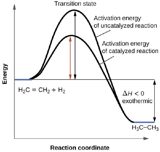
    A graph is shown with the label, “Reaction coordinate,” on the x-axis and the label,“Energy,” on the y-axis. Approximately half-way up the y-axis, a short portion of a black concave down curve which has a horizontal line extended from it across the graph. The left end of this line is labeled “H subscript 2 C equals C H subscript 2 plus H subscript 2.” The black concave down curve extends upward to reach a maximum near the height of the y-axis. The peak of this curve is labeled, “Transition state.” A double sided arrow extends from the horizontal line to the peak of the curve. This arrow is labeled, “Activation energy of Uncatalyzed reation.” From the peak, the curve continues downward to a second horizontally flattened region well below the origin of the curve near the x-axis. This flattened region is shaded in blue and is labeled “H subscript 3 C dash C H subscript 3.” A double sided arrow is drawn from the lowers part of this curve at the far right of the graph to the line extending across the graph above it. This arrow is labeled, “capital delta H less than 0 : exothermic.” A second curve is drawn with the same flattened regions at the start and end of the curve. The height of this curve is about two-thirds the height of the first curve. A double sided arrow is drawn from the horizontal line that originates at the left side of the graph to the peak of this second curve. This arrow is labeled, “Activation energy of catalyzed reaction.”
    Figura \(\PageIndex{1}\): Este gráfico compara las coordenadas de reacción para la hidrogenación de alquenos catalizados y no catalizados.

    Los catalizadores funcionan al proporcionar un mecanismo de reacción alternativo que tiene una energía de activación menor que la que se encontraría en ausencia del catalizador. En algunos casos, el mecanismo catalizado puede incluir pasos adicionales, como se muestra en los diagramas de reacción que se muestran en la Figura \(\PageIndex{2}\). Esta energía de activación más baja resulta en un aumento en la velocidad como se describe en la ecuación de Arrhenius. Tenga en cuenta que un catalizador disminuye la energía de activación para las reacciones directas e inversas y, por lo tanto, acelera las reacciones directas e inversas. En consecuencia, la presencia de un catalizador permitirá que un sistema alcance el equilibrio más rápidamente, pero no tiene efecto en la posición del equilibrio como se refleja en el valor de su constante de equilibrio (vea el capítulo posterior sobre el equilibrio químico).
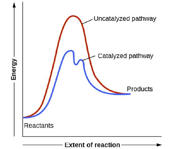
    A graph is shown with the label, “Extent of reaction,” appearing in a right pointing arrow below the x-axis and the label, “Energy,” in an upward pointing arrow just left of the y-axis. Approximately one-fifth of the way up the y-axis, a very short, somewhat flattened portion of both a red and a blue curve are shown. This region is labeled “Reactants.” A red concave down curve extends upward to reach a maximum near the height of the y-axis. This curve is labeled, “Uncatalyzed pathway.” From the peak, the curve continues downward to a second horizontally flattened region at a height of about one-third the height of the y-axis. This flattened region is labeled, “Products.” A second curve is drawn in blue with the same flattened regions at the start and end of the curve. The height of this curve is about two-thirds the height of the first curve and just right of its maximum, the curve dips low, then rises back and continues a downward trend at a lower height, but similar to that of the red curve. This blue curve is labeled, “Catalyzed pathway.”
    Figura \(\PageIndex{2}\): Este diagrama de energía potencial muestra el efecto de un catalizador en la energía de activación. El catalizador proporciona un curso de reacción diferente con una energía de activación más baja. Como se muestra, la reacción catalizada involucra un mecanismo de dos pasos (tenga en cuenta la presencia de dos estados de transición) y una especie intermedia (representada por el valle entre los dos estados de transición).

    Ejemplo \(\PageIndex{1}\): USANDO LOS DIAGRAMAS DE REACCIÓN PARA COMPARAR REACCIONES CATALIZADAS

    Los dos diagramas de la reacción aquí representan la misma reacción: una reacción sin catalizador y otra reacción con catalizador. Identifique cuál de los diagramas sugieren la presencia de un catalizador y determine la energía de activación para la reacción catalizada.
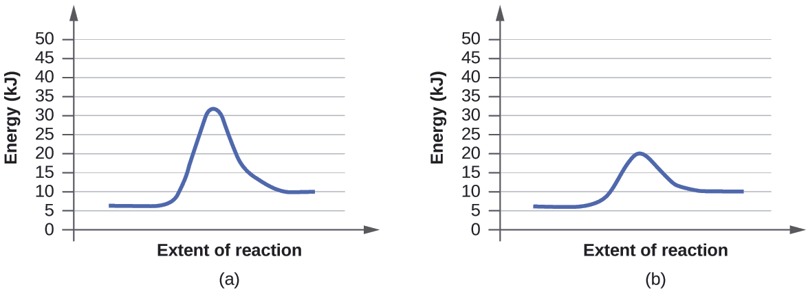
    In this figure, two graphs are shown. The x-axes are labeled, “Extent of reaction,” and the y-axes are labeled, “Energy ( k J ).” The y-axes are marked off from 0 to 50 in intervals of five. In a, a blue curve is shown. It begins with a horizontal segment at about 6. The curve then rises sharply near the middle to reach a maximum of about 32 and similarly falls to another horizontal segment at about 10. In b, the curve begins and ends similarly, but the maximum reached near the center of the graph is only 20.

    Solución

    Un catalizador no afecta la energía del reactivo o del producto, por lo que esos aspectos de los diagramas se pueden ignorar; son como esperaríamos, idénticos a ese respecto. Sin embargo, hay una diferencia notable en el estado de transición, que es claramente inferior en el diagrama (b) que en (a). Esto indica el uso de un catalizador en el diagrama (b). La energía de activación es la diferencia entre la energía de los reactivos de partida y el estado de transición, un máximo en el diagrama de coordenadas de reacción. Los reactivos están a 6 kJ y el estado de transición está a 20 kJ, por lo que la energía de activación se puede calcular de la siguiente manera:

    \[E_\ce{a}=\mathrm{20\:kJ−6\:kJ=14\:kJ} \label{12.8.1}\]

    Ejercicio \(\PageIndex{1}\)

    Determine cuál de los dos diagramas aquí (ambos para la misma reacción) involucra un catalizador e identifique la energía de activación para la reacción catalizada:
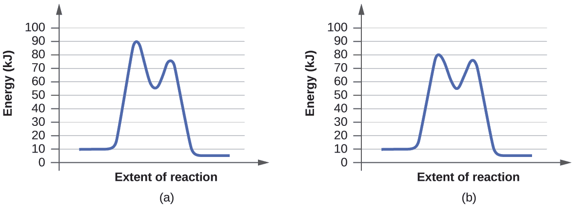
    In this figure, two graphs are shown. The x-axes are labeled, “Extent of reaction,” and the y-axes are labeledc “Energy (k J).” The y-axes are marked off from 0 to 100 at intervals of 10. In a, a blue curve is shown. It begins with a horizontal segment at about 10. The curve then rises sharply near the middle to reach a maximum of about 91, then sharply falls to about 52, again rises sharply to about 73 and falls to another horizontal segment at about 5. In b, the curve begins and ends similarly, but the first peak reaches about 81, drops to about 55, then rises to about 77 before falling to the horizontal region at about 5.

    Respuesta

    El diagrama (b) es una reacción catalizada con una energía de activación de aproximadamente 70 kJ.

    Catalizadores Homogéneos

    Un catalizador homogéneo está presente en la misma fase que los reactivos. Interactúa con un reactivo para formar una sustancia intermedia, que luego se descompone o reacciona con otro reactivo en uno o más pasos para regenerar el catalizador original y formar el producto. Como una ilustración importante de la catálisis homogénea, considere la capa de ozono de la tierra. El ozono en la atmósfera superior, que protege la tierra de la radiación ultravioleta, se forma cuando las moléculas de oxígeno absorben la luz ultravioleta y reaccionan:

    \[\ce{3O2}(g)\xrightarrow{hv}\ce{2O3}(g) \label{12.8.2}\]

    El ozono es una molécula relativamente inestable que se descompone para producir el oxígeno diatómico por el reverso de esta ecuación. Esta reacción de descomposición es consistente con el siguiente mecanismo:

    \[\ce{O3 ⟶ O2 + O\\
    O + O3 ⟶ 2O2} \label{12.8.3}\]

    La presencia del óxido nítrico, NO, influye la velocidad de descomposición del ozono. El óxido nítrico actúa como un catalizador en el siguiente mecanismo:

    \[\ce{NO}(g)+\ce{O3}(g)⟶\ce{NO2}(g)+\ce{O2}(g)\\
    \ce{O3}(g)⟶\ce{O2}(g)+\ce{O}(g)\\
    \ce{NO2}(g)+\ce{O}(g)⟶\ce{NO}(g)+\ce{O2}(g) \label{12.8.4}\]

    El cambio químico general para el mecanismo catalizado es el mismo que:

    \[\ce{2O3}(g)⟶\ce{3O2}(g) \label{12.8.5}\]

    El óxido nítrico reacciona y se regenera en estas reacciones. No se usa permanentemente; por lo tanto, actúa como un catalizador. La velocidad de la descomposición del ozono es más rápida en la presencia del óxido nítrico debido a la actividad catalítica del NO. Ciertos compuestos que contienen cloro también catalizan la descomposición del ozono.

    Mario J. Molina

    El Premio Nobel de Química de 1995 fue compartido por Paul J. Crutzen, Mario J. Molina (Figura \(\PageIndex{3}\)) y F. Sherwood Rowland "por su trabajo en la química atmosférica, particularmente en respecto a la formación y descomposición del ozono ." Molina, ciudadano mexicano, hizo la mayoría de su trabajo en el Instituto Tecnológico de Massachusetts (MIT).
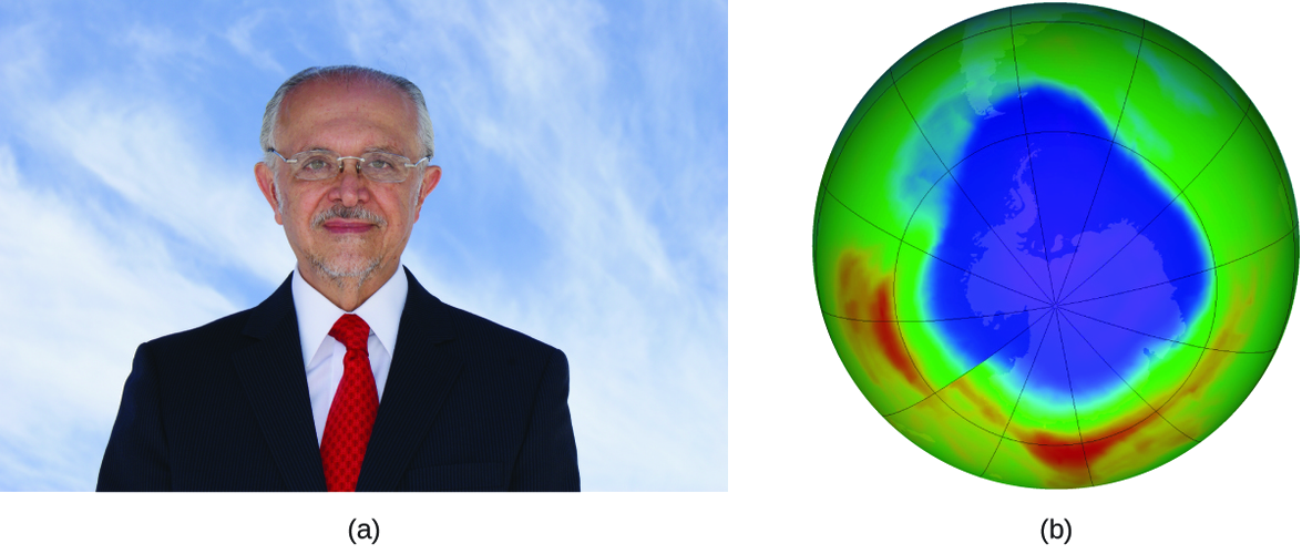
    A photograph is shown of Mario Molina. To the right of the photo, an image of Earth’s southern hemisphere is shown with a central circular region in purple with a radius of about half that of the entire hemisphere. Just outside this region is a narrow royal blue band, followed by an outer thin turquoise blue band. The majority of the outermost region is green. Two small bands of yellow are present in the lower regions of the image.
    Figura \(\PageIndex{3}\): (a) El químico mexicano Mario Molina (1943 -) compartió el Premio Nobel de Química en 1995 por su investigación sobre (b) el agujero de ozono antártico. (crédito a: cortesía de Mario Molina; crédito b: modificación del trabajo de la NASA)

    En 1974, Molina y Rowland publicaron un artículo en la revista de Nature (una de las principales publicaciones revisadas en el campo de la ciencia) que detalla la amenaza de los gases de clorofluorocarbono para la estabilidad de la capa de ozono en la atmósfera superior de la Tierra. La capa de ozono protege la tierra de la radiación solar al absorber la luz ultravioleta. A medida que las reacciones químicas agotan la cantidad de ozono en la atmósfera superior, se forma un "agujero" medible sobre la Antártida, y un aumento en la cantidad de radiación ultravioleta solar, fuertemente relacionada con la prevalencia de cánceres de piel, llega a la superficie de la Tierra. El trabajo de Molina y Rowland fue instrumental en la adopción del Protocolo de Montreal, un tratado internacional firmado en 1987 que comenzó a eliminar con éxito la producción de los productos químicos relacionados con la destrucción del ozono.

    Molina y Rowland demostraron que los átomos de cloro de los químicos producidos por el hombre pueden catalizar la destrucción del ozono en un proceso similar al cual NO acelera el agotamiento del ozono. Los átomos de cloro se generan cuando los clorocarbonos o los clorofluorocarbonos, una vez ampliamente usados como refrigerantes y propulsores, se descomponen fotoquímicamente por la luz ultravioleta o reaccionan con los radicales hidroxilos. Aquí se muestra un mecanismo de muestra usando el cloruro de metilo:

    \[\ce{CH3Cl + OH ⟶ Cl + other\: products}\]

    Los radicales de cloro descomponen el ozono y se regeneran mediante el siguiente ciclo catalítico:

    \[\ce{Cl + O3 ⟶ ClO + O2}\\
    \ce{ClO + O ⟶ Cl + O2}\\
    \textrm{overall Reaction: }\ce{O3 + O ⟶ 2O2}\]

    Un solo cloro monoatómico se puede descomponer en miles de moléculas de ozono. Afortunadamente, la mayoría del cloro atmosférico existe como formas catalíticamente inactivas de Cl2 y ClONO2.

    Deficiencia de glucosa-6-fosfato deshidrogenasa

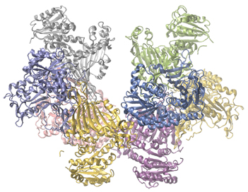
    Las enzimas en el cuerpo humano actúan como catalizadores de importantes reacciones químicas. Deficiencia de glucosa-6-fosfato deshidrogenasain metabolismo celular. Como tal, una deficiencia de una enzima particular puede resultar en una enfermedad que potencialmente puede causar la muerte. La deficiencia de G6PD (glucosa-6-fosfato deshidrogenasa), es una condición genética que resulta en una escasez de la enzima glucosa-6-fosfato deshidrogenasa y es la deficiencia enzimática más común en humanos. Esta enzima, que se muestra en la Figura \(\PageIndex{4}\), es la enzima limitante de la velocidad de la ruta metabólica que suministra NADPH a las células (Figura \(\PageIndex{5}\)).

    A colorful model of the Glucose-6-phosphate dehydrogenase structure is shown. The molecule has two distinct lobes which are filled with spiraled ribbon-like regions of yellow, lavender, blue, silver, green, and pink.
    Figura \(\PageIndex{4}\): La glucosa-6-fosfato deshidrogenasa es una enzima limitante de la velocidad de la vía metabólica que suministra NADPH a las células.

    Una interrupción en esta reacción metabólica puede causar una reducción del glutatión en los glóbulos rojos; una vez que se consume todo el glutatión, las enzimas y otras proteínas, como la hemoglobina, son susceptibles al daño. Por ejemplo, la hemoglobina se puede metabolizar y formar la bilirrubina, lo que conduce a ictericia, una afección que se puede volver grave. Las personas que sufren de la deficiencia de G6PD deben evitar ciertos alimentos y medicamentos que contienen productos químicos que pueden provocar daños en sus glóbulos rojos deficientes en glutatión.
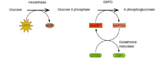
    A reaction mechanism is diagrammed in this figure. At the left, the name Glucose is followed by a horizontal, right pointing arrow, labeled, “Hexokinase.” Below this arrow and to the left is a yellow star shape labeled, “A T P.” A curved arrow extends from this shape to the right pointing arrow, and down to the right to a small brown oval labeled, “A D P.” To the right of the horizontal arrow is the name Glucose 6 phosphate, which is followed by another horizontal, right pointing arrow which is labeled, “G 6 P D.” A small orange rectangle below and left of this arrow is labeled “N A D P superscript plus.” A curved arrow extends from this shape to the right pointing arrow, and down to the right to a small salmon-colored rectangle labeled “N A P D H.” A curved arrow extends from this shape below and to the left, back to the orange rectangle labeled, “N A D P superscript plus.” Another curved arrow extends from a green oval labeled “G S S G” below the orange rectangle, up to the arrow curving back to the orange rectangle. This last curved arrow continues on to the lower right to a second green oval labeled, “G S H.” The end of this curved arrow is labeled, “Glutathione reductase.” To the right of the rightmost horizontal arrow appears the name 6 phosphogluconate.
    Figura \(\PageIndex{5}\): En el mecanismo de la reacción del curso de la pentosa fosfato, G6PD cataliza la reacción que regula la NAPDH, una coenzima que regula el glutatión, un antioxidante que protege los glóbulos rojos y otras células del daño oxidativo.

    Los catalizadores heterogéneos

    Un catalizador heterogéneo es un catalizador que está presente en una fase diferente (generalmente un sólido) que los reactivos. Tales catalizadores generalmente funcionan al proporcionar una superficie activa sobre la cual puede ocurrir una reacción. Las reacciones en la fase gaseosa y líquida catalizadas por los catalizadores heterogéneos ocurren en la superficie del catalizador en lugar de dentro de la fase gaseosa o líquida.

    La catálisis heterogénea tiene al menos cuatro pasos:

    1. Adsorción del reactivo sobre la superficie del catalizador.
    2. Activación del reactivo adsorbido.
    3. Reacción del reactivo adsorbido
    4. Difusión del producto desde la superficie hacia la fase gaseosa o líquida (desorción).

    Cualquiera de estos pasos puede ser lento y, por lo tanto, puede servir como el paso determinante de la velocidad. Sin embargo, en general, en presencia del catalizador, la velocidad general de la reacción es más rápida de lo que sería si los reactivos estuvieran en la fase gaseosa o líquida.

    La Figura \(\PageIndex{6}\) ilustra los pasos que los químicos creen que ocurren en la reacción de los compuestos que contienen un doble enlace carbono-carbono con hidrógeno en un catalizador de níquel. El níquel es el catalizador que se usa en la hidrogenación de grasas y aceites poliinsaturados (que contienen varios enlaces dobles carbono-carbono) para producir grasas y aceites saturados (que contienen solo enlaces simples carbono-carbono).
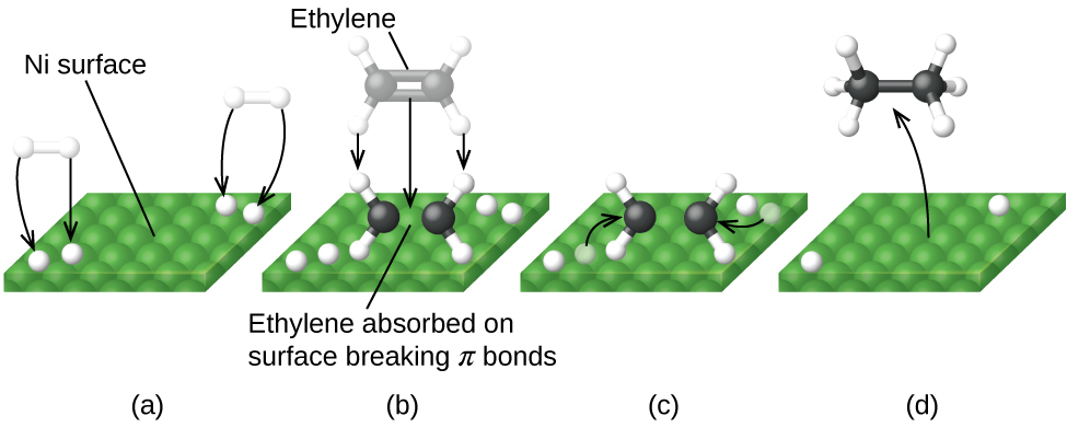
    In this figure, four diagrams labeled a through d are shown. In each, a green square surface is shown in perspective to provide a three-dimensional appearance. In a, the label “N i surface” is placed above with a line segment extending to the green square. At the lower left and upper right, pairs of white spheres bonded tougher together appear as well as white spheres on the green surface. Black arrows are drawn from each of the white spheres above the surface to the white sphere on the green surface. In b, the white spheres are still present on the green surface. Near the center of this surface is a molecule with two central black spheres with a double bond indicated by two horizontal black rods between them. Above and below to the left and right, a total of four white spheres are connected to the black spheres with white rods. A line segment extends from this structure to the label, “Ethylene absorbed on surface breaking pi bonds.” Just above this is a nearly identical structure greyed out with three downward pointing arrows to the black and white structure to indicate downward motion. The label “Ethylene” at the top of the diagram is connected to the greyed out structure with a line segment. In c, the diagram is very similar to b except that the greyed out structure and labels are gone and one of the white spheres near the black and white structure in each pair on the green surface is greyed out. Arrows point from the greyed out white spheres to the double bond between the two black spheres. In d, only a single white sphere remains from each pair in the green surface. A curved arrow points from the middle of the green surface to a model above with two central black spheres with a single black rod indicating a single bond between them. Each of the black rods has three small white spheres bonded as indicated by white rods between the black spheres and the small white spheres. The four bonds around each black sphere are evenly distributed about the black spheres.
    Figura \(\PageIndex{6}\): Hay cuatro pasos en la catálisis de la reacción \(\ce{C2H4+H2⟶ C2H6}\) por níquel. (a) El hidrógeno se adsorbe en la superficie, rompiendo los enlaces de H – H y formando enlaces de Ni – H. (b) El etileno se adsorbe en la superficie, rompiendo el enlace π y formando enlaces de Ni – C. (c) Los átomos se difunden por la superficie y forman nuevos enlaces de CH cuando chocan. (d) Las moléculas C2H6 escapan de la superficie del níquel, ya que no son fuertemente atraídas por el níquel.

    Otros importantes procesos industriales que involucran el uso de los catalizadores heterogéneos incluyen la preparación del ácido sulfúrico, la preparación del amoníaco, la oxidación del amoníaco al ácido nítrico y la síntesis del metanol, CH3OH. Los catalizadores heterogéneos también se usan en los convertidores catalíticos que se encuentran en la mayoría de los automóviles que funcionan con la gasolina (Figura \(\PageIndex{7}\)).

    CONVERTIDORES CATALÍTICOS DE los automóviles

    Los científicos desarrollaron los convertidores catalíticos para reducir la cantidad de emisiones tóxicas producidas al quemar gasolina en los motores de combustión interna. Los convertidores catalíticos aprovechan los cinco factores que afectan la velocidad de las reacciones químicas para garantizar que las emisiones de escape sean lo más seguras posible.

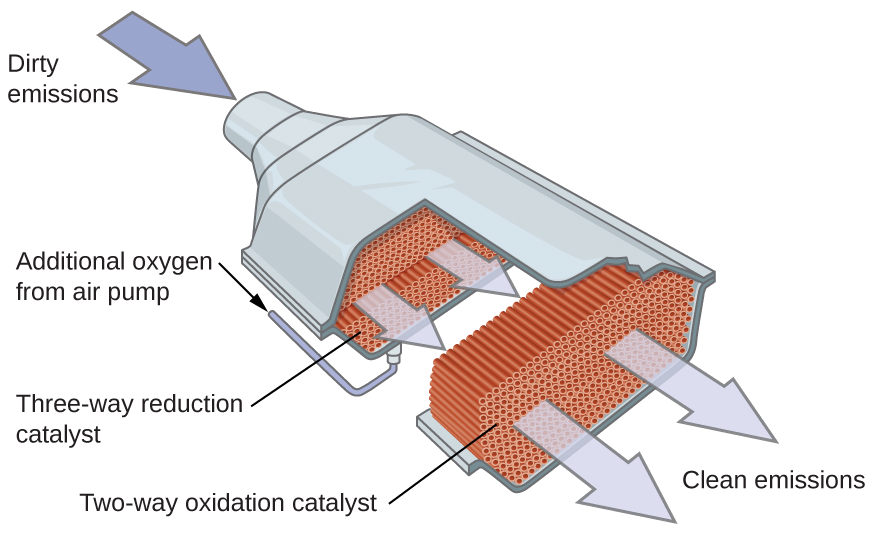
    Al usar una mezcla cuidadosamente seleccionada de metales catalíticamente activos, es posible llevar a cabo la combustión completa de todos los compuestos que contienen carbono en dióxido de carbono al tiempo que se reduce la producción de los óxidos de nitrógeno. Esto es particularmente impresionante cuando consideramos que un paso involucra la adición de más oxígeno a la molécula y el otro involucra eliminar el oxígeno (Figura \(\PageIndex{6}\)).

    An image is shown of a catalytic converter. At the upper left, a blue arrow pointing into a pipe that enters a larger, widened chamber is labeled, “Dirty emissions.” A small black arrow that points to the lower right is positioned along the upper left side of the widened region. This arrow is labeled, “Additional oxygen from air pump.” The image shows the converter with the upper surface removed, exposing a red-brown interior. The portion of the converter closest to the dirty emissions inlet shows small, round components in an interior layer. This layer is labeled “Three-way reduction catalyst.” The middle region shows closely packed small brown rods that are aligned parallel to the dirty emissions inlet pipe. The final quarter of the interior of the catalytic converter again shows a layer of closely packed small red brown circles. Two large light grey arrows extend from this layer to the open region at the lower right of the image to the label “Clean emissions.”
    Figura \(\PageIndex{6}\): Un convertidor catalítico permite la combustión de todos los compuestos que contienen carbono en dióxido de carbono y al mismo tiempo reduciendo la producción del óxido de nitrógeno y otros contaminantes en las emisiones de los motores que queman la gasolina.

    Los convertidores catalíticos más modernos de tres vías poseen una superficie impregnada con un catalizador de platino-rodio, que cataliza la conversión del óxido nítrico al dinitrógeno y oxígeno, así como la conversión del monóxido de carbono e hidrocarburos como el octano en dióxido de carbono y vapor de agua:

    \[\ce{2NO2}(g)⟶\ce{N2}(g)+\ce{2O2}(g)\\ [5pt]
    \ce{2CO}(g)+\ce{O2}(g)⟶\ce{2CO2}(g)\\ [5pt]
    \ce{2C8H18}(g)+\ce{25O2}(g)⟶\ce{16CO2}(g)+\ce{18H2O}(g)\]

    Para ser lo más eficiente posible, la mayoría de los convertidores catalíticos son precalentados por un calentador eléctrico. Esto asegura que los metales en el catalizador estén completamente activos incluso antes de que el escape del automóvil esté lo suficientemente caliente como para mantener las temperaturas de reacción apropiadas.

    Estructura y función de las enzimas

    El estudio de las enzimas es una interconexión importante entre la biología y la química. Las enzimas son generalmente proteínas (polipéptidos) que ayudan a controlar la velocidad de las reacciones químicas entre los compuestos biológicamente importantes, particularmente aquellos que están involucrados en el metabolismo celular. Las diferentes clases de enzimas realizan una variedad de funciones, como se muestra en la Tabla \(\PageIndex{1}\).

    Tabla \(\PageIndex{1}\): Clases de enzimas y sus funciones
    Clase Función
    oxidorreductasas reacciones redox
    transferasas transferencia de grupos funcionales
    hidrolasas reacciones de hidrólisis
    liasa eliminación grupal para formar dobles enlaces
    isomerasas isomerización
    ligases formación de enlaces con hidrólisis de ATP

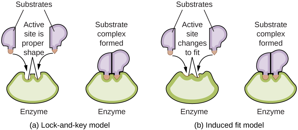
    Las moléculas de las enzimas poseen un sitio activo, una parte de la molécula con una forma que le permite unirse a un sustrato específico (una molécula reactiva), formando un complejo enzima-sustrato como un intermedio de la reacción. Hay dos modelos que intentan explicar cómo funciona este sitio activo. El modelo más simplista se conoce como la hipótesis de la cerradura y la llave, lo que sugiere que las formas moleculares del sitio activo y el sustrato son complementarias, encajando juntas como una llave en una cerradura. La hipótesis de ajuste inducido, por otro lado, sugiere que la molécula enzimática es flexible y cambia de forma para acomodar un enlace con el sustrato. Sin embargo, esto no sugiere que el sitio activo de una enzima sea completamente maleable. Tanto el modelo de cerradura y llave como el modelo de ajuste inducido explican el hecho de que las enzimas solo se pueden unir con sustratos específicos, ya que en general una enzima particular solo cataliza una reacción particular (Figura \(\PageIndex{7}\)).

    A diagram is shown of two possible interactions of an enzyme and a substrate. In a, which is labeled “Lock-and-key,” two diagrams are shown. The first shows a green wedge-like shape with two small depressions in the upper surface of similar size, but the depression on the left has a curved shape, and the depression on the right has a pointed shape. This green shape is labeled “Enzyme.” Just above this shape are two smaller, irregular, lavender shapes each with a projection from its lower surface. The lavender shape on the left has a curved projection which matches the shape of the depression on the left in the green shape below. This projection is shaded orange and has a curved arrow extending from in to the matching depression in the green shape below. Similarly, the lavender shape on the right has a projection with a pointed tip which matches the shape of the depression on the right in the green shape below. This projection is shaded orange and has a curved arrow extending from in to the matching depression in the green shape below. Two line segments extend from the depressions in the green shape to form an inverted V shape above the depressions. Above this and between the lavender shapes is the label, “Active site is proper shape.” The label “Substrates” is at the very top of the diagram with line segments extending to the two lavender shapes. To the right of this diagram is a second diagram showing the lavender shapes positioned next to each other, fit snugly into the depressions in the green shape, which is labeled “Enzyme.” Above this diagram is the label, “Substrate complex formed.” In b, which is labeled “Induced fit,” two diagrams are shown. The first shows a green wedge-like shape with two small depressions in the upper surface of similar size, but irregular shape. This green shape is labeled “Enzyme.” Just above this shape are two smaller irregular lavender shapes each with a projection from its lower surface. The lavender shape on the left has a curved projection. This projection is shaded orange and has a curved arrow extending from it to the irregular depression just below it in the green shape below. Similarly, the lavender shape on the right has a projection with a pointed tip. This projection is shaded orange and has a curved arrow extending from it to the irregular depression just below it in the green shape below. Two line segments extend from the depressions in the green shape to form an inverted V shape above the depressions. Above this and between the lavender shapes is the label, “Active site changes to fit.” The label, “Substrates” is at the very top of the diagram with line segments extending to the two lavender shapes. To the right of this diagram is a second diagram showing the purple shapes positioned next to each other, fit snugly into the depressions in the green shape, which is labeled “Enzyme.” Above this diagram is the label “Substrate complex formed.” The projections from the lavender shapes match the depression shapes in the green shape, resulting in a proper fit.
    Figura \(\PageIndex{7}\): (a) Según el modelo de cerradura y llave, la forma del sitio activo de una enzima es perfecta para el sustrato. (b) Según el modelo de ajuste inducido, el sitio activo es algo flexible y puede cambiar de forma para unirse con el sustrato.​​​​​​​

    Resumen

    Los catalizadores afectan la velocidad de una reacción química al alterar su mecanismo para proporcionar una energía de activación más baja. Los catalizadores pueden ser homogéneos (en la misma fase que los reactivos) o heterogéneos (una fase diferente a los reactivos)

    Notas al pie de la página

    1. "El Premio Nobel de Química 1995", Premio Nobel.org, consultado el 18 de febrero de 2015, http://www.nobelprize.org/nobel_priz...aureates/1995/.

    Glosario

    catalizador heterogéneo
    catalizador presente en una fase diferente de los reactivos, proporcionando una superficie en la que puede ocurrir una reacción
    catalizador homogéneo
    catalizador presente en la misma fase que los reactivos

    Contribuyentes

    • Paul Flowers (Universidad de Carolina del Norte - Pembroke), Klaus Theopold (Universidad de Delaware) y Richard Langley (Stephen F. Austin Universidad del Estado) con autores contribuyentes. Contenido del libro de texto producido por la Universidad de OpenStax tiene licencia de Atribución de Creative Commons Licencia 4.0 licencia. Descarge gratis en http://cnx.org/contents/85abf193-2bd...a7ac8df6@9.110)."

    • Ana Martinez (amartinez02@saintmarys.edu) contribuyó a la traducción de este texto.


    This page titled 12.8: El catálisis is shared under a CC BY license and was authored, remixed, and/or curated by OpenStax.